| Version 6 (modified by chunter, 9 years ago) (diff) |
|---|
802.11 Reference Design
- Download
- Changelog
- FAQ
- Architecture
Using the Design...
Benchmarks
- IFS Calibration
- Throughput
- Transmitter Characterization
- Receiver Characterization
- Pkt. Det. Min. Power Characterization
MAC
- PHY
Experiments Framework...
- Packet Flow
- FPGA Architecture
- FPGA Resource Usage
- App Notes
- Other Resources
- License
- Changelog
MAC Support Core
In addition to the state implemented in the CPU_LOW processor, certain time critical MAC behaviors are implemented directly in the FPGA fabric via the MAC Support Core. This core was designed to meet the needs of the DCF implementation of 802.11 while still remaining flexible for custom applications. There are three basic components to the peripheral: Timers, MAC Tx Controller A, MAC Tx Controller B.
Timers
Many MAC algorithms require precise scheduling of transmissions relative to some preceding transmission or reception event. Examples in the DCF include the following:
- ACK and CTS transmissions must occur a SIFS period after previous qualified receptions
- Contention windows must begin a timeout interval after a previous unsuccessful transmission
To enable these and other custom applications, we have designed the hardware with 4 independent timers that can be configured via software in CPU_LOW:
- postRxTimer1
- postRxTimer2
- postTxTimer1
- postTxTimer2
These timers each independently begin after the prior transmission or reception. They count until a user-specified interval of time has elapsed and then assert an output to the MAC Tx Controller A and MAC Tx Controller B subsystems. In the stock DCF implementation of the Mango 802.11 Reference Design, only postTxTimer2 and postRxTimer1 are used. Their durations are set to a ACK timeout and a SIFS respectively. One future straightforward extension to the design would be to use postTxTimer1 to enable the "burst" transmission capabilities introduced in the 802.11e amendment where each transmission is separated by a deterministic SIFS or RIFS interval.
MAC Tx Controller A
Tx Controller A is capable of honoring a post-Tx timeout interval in which a reception is expected by the MAC state. The DCF implementation uses this controller for three different purposes:
- Transmission of "short" MPDU frames (i.e. MPDUs that required no RTS medium reservation)
- Transmission of RTS frames
- Transmission of "long" MPDU frames (i.e. MPDUs that were preceded by an RTS/CTS handshake)
The unifying trait of each of the above transmissions is the need for a post-Tx timeout window during which a response is expected.
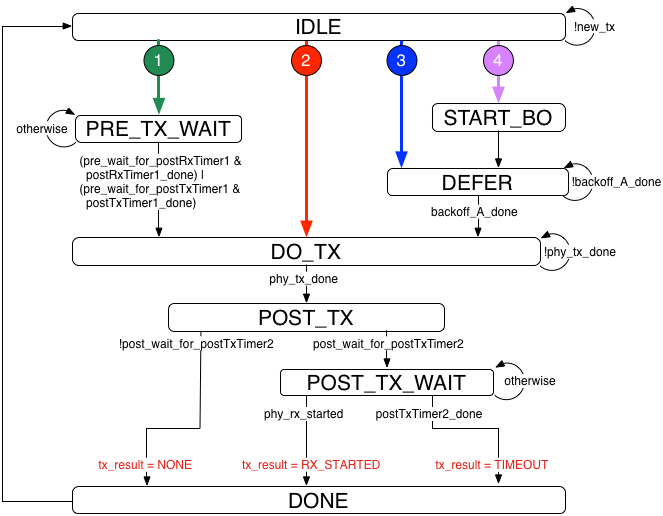
Implementation Details

The above image gives a more detailed view on the state machine implemented in Tx Controller A. Prior to actually transmitting, the controller is capable of starting a backoff or deferring to an already running backoff when the medium is not idle. Alternatively, it can wait for a deterministic interval before transmitting. This interval is defined by either the postRxTimer1 or postTxTimer1 timers described above.
For the DCF implementation, short MPDU and RTS transmissions do not employ the green deterministic-wait state. These transmission do employ the purple and blue backoff deferral states. Long MPDU transmissions, however, must occur a deterministic SIFS interval after the previous CTS reception. As such, these transmissions use the green deterministic-wait states.
MAC Tx Controller B
The Tx Controller B is simpler than Tx Controller A. After a transmission is complete, the controller is done and does not need to start any kind of post-Tx timeout interval. Optionally, Tx Controller B can condition its transmission on medium idleness. The DCF implementation uses this controller for two purposes:
- Transmission of CTS frames
- Transmission of ACK frames
Both of the above transmissions have the common trait of being "fire and forget." They are slightly different from one another in that ACK frames must be transmitted regardless of perceived medium busyness. This is not the case for CTS frames, which are only sent when the medium is deemed idle.
Implementation Details

Like Tx Controller A, the green section of the above state machine forces the controller to wait for a deterministic amount of time prior to a transmission. The DCF uses this to schedule CTS and ACK transmissions a SIFS interval after the previous reception. The CTS case additionally instructs the controller to condition transmission on medium idleness.
Attachments (7)
- tx_fsm_transition_1.png (1.7 KB) - added by murphpo 8 years ago.
- tx_fsm_transition_2.png (1.7 KB) - added by murphpo 8 years ago.
- tx_fsm_transition_3.png (1.9 KB) - added by murphpo 8 years ago.
- tx_fsm_transition_4.png (1.8 KB) - added by murphpo 8 years ago.
- tx_fsm_a.png (59.7 KB) - added by murphpo 8 years ago.
- tx_fsm_b.png (32.5 KB) - added by murphpo 8 years ago.
- tx_fsm_cd.png (23.5 KB) - added by murphpo 7 years ago.
Download all attachments as: .zip